Maintenance costs in hazardous locations are often caused by the wrong enclosure, poor installation, moisture ingress, corrosion, incorrect cable entries, and difficult access during inspection. Selecting the right Ex e Increased Safety Enclosures at the design stage can reduce unplanned shutdowns, replacement purchases, inspection time, and safety risks.
This guide explains how purchasing teams, maintenance managers, electrical engineers, and safety specialists can select and install hazardous area enclosures that deliver lower lifetime costs. It combines the most common information users expect from leading industrial enclosure guides: hazardous area classification, certification, environmental protection, material selection, installation steps, maintenance planning, purchasing controls, and common errors to avoid.
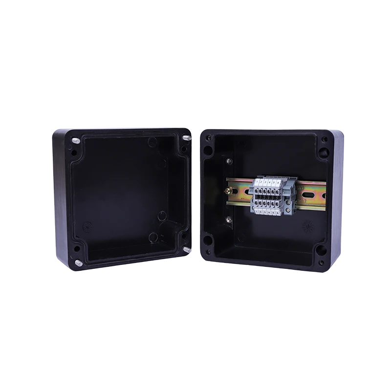
Understand Which Maintenance Costs the Enclosure Must Control
Identify the real causes of maintenance spending
The purchase price of an enclosure is only one part of its total cost. A low-cost enclosure can become expensive when it causes repeated troubleshooting, corrosion, water damage, loose terminals, or lengthy inspection work.
Before choosing a product, list the maintenance problems experienced in the installation area:
- Water, condensation, dust, or chemical contamination inside the enclosure.
- Corrosion around hinges, fasteners, cable glands, or mounting brackets.
- Cracked seals that allow hazardous gases or dust to enter.
- Overheating caused by high internal power dissipation or poor ventilation design.
- Loose terminals caused by vibration or incorrect tightening.
- Insufficient internal space that makes inspection and repair difficult.
- Non-certified cable glands or blanking plugs that invalidate the installation.
- Missing labels, drawings, or certification records that slow down inspection.
- Long replacement lead times for non-standard or imported components.
Calculate total cost of ownership instead of purchase price
Purchasing teams should compare the total cost of ownership over the expected service life. A properly specified enclosure may cost more initially but reduce labor, downtime, spare parts, and replacement frequency.
Use this cost model:
- Initial enclosure and accessory cost.
- Engineering and certification review cost.
- Installation and cable termination labor.
- Inspection and commissioning labor.
- Routine cleaning, gasket replacement, and retightening.
- Corrective maintenance and emergency callout costs.
- Production losses caused by shutdowns.
- Replacement cost and expected service life.
The best enclosure is not necessarily the cheapest product. It is the product that provides verified protection, easy maintenance, local technical support, and reliable availability throughout the operating life of the plant.
Confirm the Hazardous Area Classification Before Selecting the Enclosure
Match the enclosure to the gas or dust hazard
The first selection step is to confirm whether the installation is exposed to flammable gas, vapor, mist, combustible dust, or a combination of hazards. The enclosure protection concept and certification must match the classified location.
Collect the following information from the area classification documents:
- Gas or dust classification, such as Zone 0, Zone 1, Zone 2, Zone 20, Zone 21, or Zone 22.
- Equipment protection level, such as Ga, Gb, Gc, Da, Db, or Dc.
- Gas group or dust group.
- Temperature class or maximum surface temperature requirement.
- Ambient temperature range.
- Required ingress protection rating.
- Applicable national and international standards.
- Presence of vibration, impact, corrosive chemicals, ultraviolet light, or salt spray.
Do not select an enclosure based only on the phrase hazardous area. A Zone 1 gas installation and a Zone 22 dust installation may require different certification, temperature limits, cable entries, and installation methods.
Verify the protection concept and certificate scope
Ex e Increased Safety Enclosures are designed to prevent arcs, sparks, and excessive temperatures during normal operation. They are commonly used for terminal boxes, junction boxes, control equipment, measurement equipment, and other suitable electrical assemblies in hazardous areas.
However, the enclosure certificate does not automatically certify every component installed inside it. Verify all of the following:
- The enclosure certification covers the intended hazardous area.
- The certificate includes the required gas or dust group.
- The ambient temperature range is suitable for the site.
- The temperature class is suitable for the process environment.
- Internal terminals, fuses, relays, barriers, and other components are suitable for the protection concept.
- The cable glands, stopping plugs, breathers, drains, and accessories have compatible certification.
- The completed assembly remains within the certificate and manufacturer instructions.
Ask the supplier for the current certificate, technical datasheet, installation instructions, dimensional drawing, terminal arrangement, and applicable limitations before issuing a purchase order.
Use a Step-by-Step Enclosure Selection Process
First step: document the installation environment
Record the physical and process conditions where the enclosure will be installed. The enclosure must be suitable for both the hazardous classification and the surrounding environment.
- Indoor or outdoor installation.
- Normal and abnormal ambient temperatures.
- Rain, humidity, condensation, flooding, or washdown exposure.
- Dust accumulation and cleaning methods.
- Exposure to acids, solvents, hydrocarbons, salt, or other chemicals.
- Mechanical impact, vibration, and pressure from nearby equipment.
- Exposure to direct sunlight and ultraviolet radiation.
- Available mounting space and cable routing direction.
- Required access clearance for inspection and maintenance.
Second step: calculate the internal space requirement
List every device that will be installed inside the enclosure. Include terminals, cable loops, barriers, fuses, relays, isolators, communication modules, earth terminals, and spare terminals.
Allow additional space for safe termination and future maintenance:
- Draw the enclosure layout to scale.
- Place high-use terminals near the most accessible side.
- Separate power, signal, and intrinsically safe circuits where required.
- Provide sufficient bending radius for every cable.
- Leave room for a torque tool and test equipment.
- Reserve space for future terminals or replacement components.
- Check that the cover can be removed without disconnecting cables.
An enclosure that is too small increases installation time and makes every future inspection more difficult. A larger enclosure may reduce maintenance labor and prevent accidental damage to terminals and wiring.
Third step: select the enclosure material
Choose the material according to corrosion risk, impact requirements, weight limits, and service life.
- Stainless steel is suitable for many corrosive, outdoor, chemical, and washdown environments.
- Painted or coated metal can be suitable when the coating system matches the environment and impact requirements.
- Reinforced polymer may reduce weight and resist certain chemicals, but its temperature, impact, ultraviolet, and electrostatic properties must be verified.
- Aluminum may offer low weight and good corrosion resistance, but compatibility with the site environment must be checked.
Consider the compatibility of hinges, fasteners, mounting feet, cable glands, washers, and drain fittings. A corrosion-resistant enclosure can still fail early if lower-grade accessories are used.
Fourth step: select the ingress protection and sealing system
Choose the required IP rating based on the installation conditions and certification requirements. The rating should not be treated as a substitute for correct installation.
Check the following sealing details:
- Door or cover gasket material and temperature range.
- Gasket compression and continuity around the complete opening.
- Condition of hinges, latches, and fasteners.
- Compatibility of cable glands with the enclosure wall thickness.
- Sealing of unused entries with certified stopping plugs.
- Use of certified drains or breathers where condensation is expected.
- Protection of the enclosure during transport and storage.
Fifth step: select cable entries and internal components
Cable entries are a frequent source of water ingress, certification problems, and maintenance failures. Specify them together with the enclosure rather than treating them as separate accessories.
Confirm:
- Cable diameter range for each gland.
- Armored or unarmored cable construction.
- Material compatibility with the enclosure and cable sheath.
- Required sealing performance.
- Earth continuity requirements.
- Entry thread type and size.
- Spare entry requirements for future expansion.
- Certification and temperature range of every gland and plug.
For internal devices, confirm current, voltage, power dissipation, terminal capacity, conductor size range, creepage and clearance, short-circuit rating, and temperature rise. A certified enclosure can become unsuitable if the internal assembly is overloaded or incorrectly arranged.
Sixth step: review maintainability before ordering
Ask a maintenance technician to review the proposed layout before the purchase order is released. The technician should be able to inspect, test, tighten, replace, and document components without unnecessary disassembly.
Review these practical questions:
- Can the cover be opened safely with the installed cable routing?
- Can every terminal number be read during inspection?
- Can a torque tool reach each terminal?
- Are test points and disconnect terminals accessible?
- Can damaged glands or gaskets be replaced without replacing the entire enclosure?
- Is there enough space for spare conductors and future modifications?
- Are labels visible after installation?
Prepare the Required Tools and Documents
Tools required for installation and inspection
Prepare the correct tools before beginning work. Using improvised tools can damage threads, gaskets, cable glands, and terminal connections.
- Approved voltage tester and electrical test instruments.
- Insulated hand tools suitable for the work area.
- Calibrated torque screwdriver and torque wrench.
- Cable preparation tools and approved crimping tools.
- Gland spanners and entry thread gauges.
- Multimeter and insulation resistance tester where permitted by the equipment instructions.
- Continuity tester for protective bonding.
- Calipers or a cable diameter measurement tool.
- Level, tape measure, drill, and approved mounting hardware.
- Cleaning cloths that do not leave conductive or abrasive residue.
- Approved gasket lubricant when specified by the manufacturer.
- Camera or digital inspection system for maintenance records.
- Current drawings, certificates, installation instructions, and torque data.
Documents required before work begins
Do not start installation until the technical documentation is complete and available to the installation team.
- Hazardous area classification drawing.
- Equipment certificate and certificate schedule.
- Manufacturer installation and maintenance instructions.
- Approved enclosure layout and wiring diagram.
- Cable schedule and gland schedule.
- Inspection and test plan.
- Material certificates where required.
- Torque specifications.
- Site work permit and isolation procedure.
- Spare parts list and recommended maintenance schedule.
Install the Enclosure Correctly to Prevent Future Failures
Seventh step: inspect the enclosure before installation
Inspect the product when it arrives and record any damage before it is installed.
- Check the model number against the purchase order.
- Confirm the certification marking and nameplate information.
- Inspect the body, cover, hinges, latches, and mounting points.
- Check that the gasket is continuous, clean, and undamaged.
- Verify that cable entries and accessories match the approved drawing.
- Confirm that internal terminals and components are the specified models.
- Photograph the enclosure and store the records with the project documents.
Eighth step: mount and bond the enclosure
Mount the enclosure on a rigid, level support that can withstand the enclosure weight, cable loading, vibration, and environmental forces.
- Use mounting hardware suitable for the wall, frame, or support structure.
- Prevent distortion of the enclosure body during tightening.
- Maintain the required clearance for cover removal and inspection.
- Prevent water from collecting around the enclosure base.
- Install external and internal protective bonding as required.
- Verify electrical continuity of the protective bonding path.
- Protect the enclosure from impact caused by nearby vehicles or equipment.
Ninth step: install cable glands and terminate conductors
Install cable glands according to the manufacturer instructions and certification conditions. Incorrect gland installation can allow moisture ingress or compromise the hazardous area protection.
- Confirm the gland type and size against the cable schedule.
- Check the cable diameter and armor construction.
- Prepare the cable without damaging insulation or armor.
- Install the gland, sealing components, washers, and locknuts in the correct order.
- Tighten the gland to the specified torque.
- Seal unused entries with approved stopping plugs.
- Route conductors with the required bending radius.
- Terminate each conductor using the specified terminal and ferrule.
- Tighten terminals to the documented torque.
- Apply permanent identification to cables, terminals, and circuits.
Tenth step: test, inspect, and document the completed installation
Complete the inspection before energizing the equipment. The final record should prove that the installed assembly matches the approved design.
- Check enclosure certification and nameplate visibility.
- Inspect gasket compression and cover closure.
- Verify that all fasteners, glands, plugs, and bonding connections are secure.
- Confirm conductor identification and terminal numbering.
- Check clearances, separation, and internal component arrangement.
- Perform continuity and insulation tests where approved.
- Check for sharp edges, loose strands, damaged insulation, or cable stress.
- Record torque values and test results.
- Photograph the completed enclosure from multiple angles.
- Update the hazardous area equipment register and maintenance database.
Choose Features That Reduce Routine Maintenance Labor
Prioritize access, durability, and replacement availability
The most useful maintenance features are those that reduce the time required to find a fault, open the enclosure, complete a repair, and restore the equipment to service.
Consider specifying:
- Robust hinges and latches that maintain reliable cover compression.
- Corrosion-resistant fasteners and mounting hardware.
- Clear internal terminal numbering.
- Removable mounting plates or terminal rails where appropriate.
- Enough space for inspection and safe cable bending.
- Standardized cable entry sizes across the project.
- Replaceable gaskets and readily available spare parts.
- Drain or breather accessories for condensation control where permitted.
- Permanent stainless steel or engraved identification labels.
- Local supplier support and documented replacement lead times.
Standardize enclosures across the facility
Standardization reduces training requirements and simplifies spare parts management. Purchasing teams should avoid approving many enclosure sizes and accessory types when a smaller range can meet the technical requirements.
A standardization program can include:
- A controlled list of approved enclosure materials and sizes.
- Standard terminal types and numbering conventions.
- Standard gland manufacturers and thread sizes.
- Standard gasket and fastener specifications.
- Approved labeling and documentation formats.
- Minimum stock levels for critical spare enclosures and accessories.
Standardization should not override hazardous area requirements. Each standard product still needs to be verified for the specific zone, gas or dust group, temperature class, ambient temperature, and ingress protection requirement.
Create a preventive maintenance schedule
A preventive maintenance schedule helps identify small problems before they become safety or production failures. The frequency should follow the equipment certificate, manufacturer instructions, site risk assessment, and applicable inspection standard.
Typical inspection activities include:
- Check for corrosion, mechanical damage, and unauthorized modifications.
- Inspect gasket condition and cover compression.
- Check cable glands, stopping plugs, and entry seals.
- Look for condensation, dust accumulation, or evidence of water ingress.
- Verify labels and certification markings remain legible.
- Check bonding and earth continuity where required.
- Inspect terminals for overheating, discoloration, or looseness.
- Confirm that spare entries remain correctly sealed.
- Update inspection records and corrective action status.
Avoid Common Enclosure Selection and Installation Mistakes
Mistake one: choosing only by dimensions and price
An enclosure that physically fits may still have the wrong certification, material, temperature class, IP rating, or internal capacity. Compare technical compliance and lifetime maintenance cost before comparing price.
Mistake two: assuming the enclosure certificate covers every internal device
The completed assembly must comply with the applicable certificate and installation instructions. Verify the suitability of terminals, fuses, relays, barriers, and other components installed inside the enclosure.
Mistake three: using uncertified cable glands or blanking plugs
Non-certified accessories can compromise ingress protection and hazardous area compliance. Use accessories with the correct certification, size, material, thread, and temperature range.
Mistake four: overfilling the enclosure
Excessive internal density can cause heat buildup, poor separation, difficult inspection, and damaged conductors. Allow space for cable bending, testing, tightening, and future replacement.
Mistake five: drilling additional holes without approval
Field modifications can invalidate certification and reduce mechanical or sealing performance. Any new entry, mounting point, drain, or breather must be approved and completed according to the manufacturer and certification requirements.
Mistake six: ignoring condensation and corrosion
Outdoor enclosures may appear sealed while still accumulating condensation during temperature changes. Select suitable materials, mounting arrangements, gaskets, drains, or breathers where permitted by the certified design and environmental conditions.
Mistake seven: failing to control tightening torque
Under-tightening can cause loose terminals and leaking glands. Over-tightening can damage threads, gaskets, cable insulation, or enclosure materials. Use calibrated tools and record critical torque values.
Mistake eight: losing certificates and installation records
Missing documents increase inspection time and may delay repairs or audits. Store certificates, drawings, test results, photographs, spare parts information, and modification records in a controlled maintenance system.
Use a Purchasing Checklist Before Approving the Order
Technical compliance checklist
- Hazardous area zone or division confirmed.
- Gas or dust group confirmed.
- Equipment protection level confirmed.
- Temperature class or maximum surface temperature confirmed.
- Ambient temperature range confirmed.
- Required IP rating confirmed.
- Material compatibility reviewed.
- Internal heat dissipation checked.
- Enclosure size and spare capacity confirmed.
- Cable gland and stopping plug schedule approved.
- Internal components verified for compatibility.
- Certificate and installation instructions received.
Maintenance and commercial checklist
- Gaskets, latches, hinges, and fasteners are replaceable or available.
- Common spare parts have acceptable lead times.
- Enclosure dimensions are compatible with existing supports.
- Maintenance access has been reviewed by site personnel.
- Supplier provides technical support and replacement documentation.
- Standardized models are used where technically appropriate.
- Product records can be added to the equipment register.
- Warranty terms cover the intended environment and installation conditions.
- Total cost of ownership has been compared with alternative products.
Reduce Lifetime Cost with the Right Ex e Enclosure Partner
Select a supplier that supports the complete lifecycle
Reliable hazardous area protection depends on more than the enclosure shell. The supplier should support specification, certification review, accessory selection, installation, inspection, and long-term replacement.
When evaluating a supplier such as MASCO, ask for:
- Current product certificates and technical files.
- Clear hazardous area application guidance.
- Material, sealing, and temperature information.
- Internal layout and terminal options.
- Certified cable gland and accessory recommendations.
- Installation, inspection, and maintenance instructions.
- Custom enclosure and labeling capabilities where required.
- Spare parts availability and realistic delivery times.
- Technical support for project approval and site questions.
Make the final selection based on reliability and maintainability
The correct enclosure selection process begins with the hazardous area classification and ends with a documented, inspectable, maintainable installation. Choosing the correct material, certificate, sealing system, cable accessories, internal layout, and spare parts strategy can reduce unplanned downtime and lower maintenance labor throughout the facility lifecycle.
For hazardous locations, Ex e Increased Safety Enclosures should be selected and installed according to the applicable certification, manufacturer instructions, and site engineering requirements. MASCO can help purchasing and engineering teams evaluate enclosure materials, sizes, certification requirements, cable entries, and maintenance considerations so the final solution provides dependable protection with a lower lifetime cost.


